
Demonstration
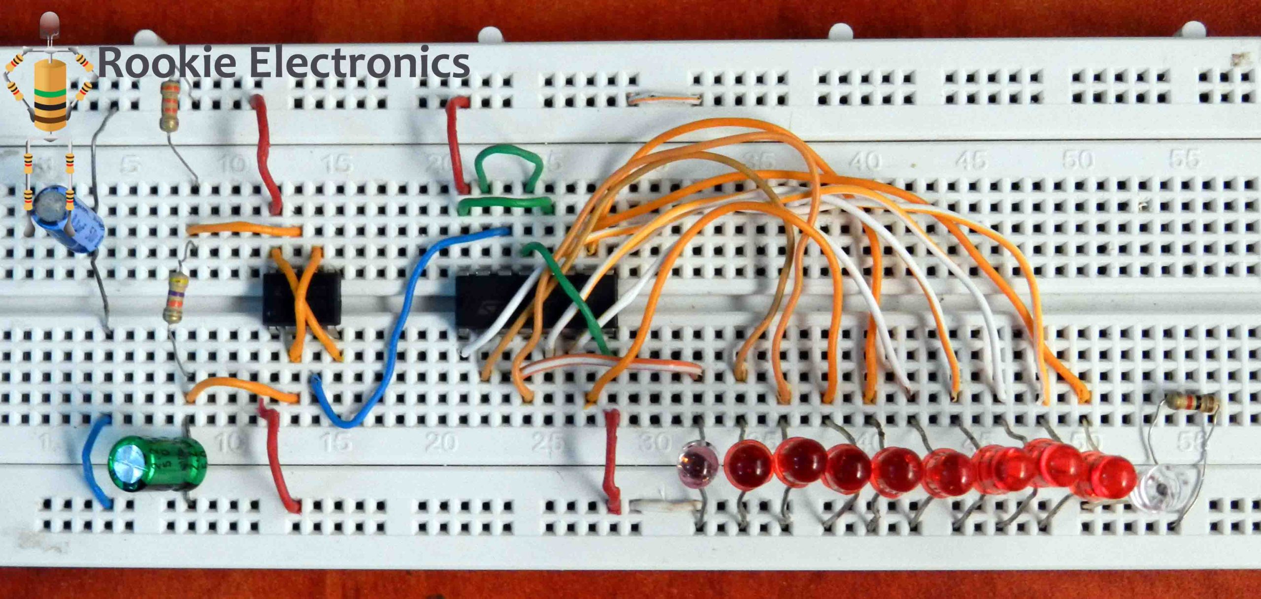
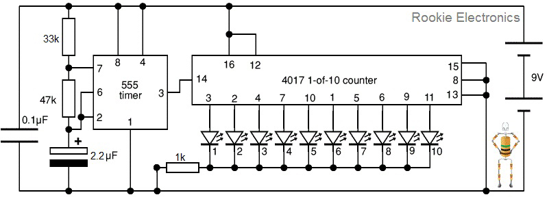
This is a sequential circuit design, it has 10 LEDs
The count advances as the clock input from 555 timer becomes high (on the rising-edge). Each output Q0-Q9 goes high in turn as counting advances.
The reset input should be low (0V) for normal operation (counting 0-9).
If you just want to use few LEDs just to have a look at function, counting to less than 9 is achieved by connecting the relevant output (Q0-Q9) to reset, for example to count 0,1,2,3 connect Q4 to reset.
Parts Required
- 33k, 47k & 1k.
- 0.1mF
- 2.2mF
- 555 Timer IC
- 4017 Counter IC
- Led x(10)
- 9v Battery
Circuit Diagram
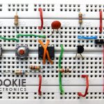
Bread board Arrangement
IC Pin Configuration